Home › Unlabelled ›
Diagram Of A Series And Parallel Circuit : Wiring Leds Correctly Series Parallel Circuits Explained - Make sure to label the following they must have a working series circuit or a working parallel circuit with a switch in their project.
Diagram Of A Series And Parallel Circuit : Wiring Leds Correctly Series Parallel Circuits Explained - Make sure to label the following they must have a working series circuit or a working parallel circuit with a switch in their project.. Serial circuit and parallel circuit and current flow in it. When constructing a parallel circuit, we say that components are connected in parallel. Locate the junctions, where three or. Like the series rlc circuit, we can solve this circuit using the phasor or vector method but this time the vector diagram will have the voltage as its reference with the three current vectors plotted with respect to the voltage. The two simplest of these are called series and parallel and occur frequently.
In a series circuit, the multiple components are connected in a cascaded manner i.e., the tail of a component is connected to the head of the other. Each time it leaves the negative pole of your car battery, it has a bewildering variety of also, schematic mode will help get you accustomed to circuit diagrams. But the pictorial view is a bit nicer to look at. Each arrangement provides a different way for electricity to flow through a circuit. The schematic diagram of the above circuit showing the electronic symbols for the battery, and bulbs is shown below.
Series And Parallel Circuits Series Vs Parallel Difference Between Series And Parallel Circuits Youtube from i.ytimg.com Locate the junctions, where three or. And the more work you have a series circuit do, the more your current will decrease. There are two basic types of electrical circuits; Draw a diagram of the circuit. Each time it leaves the negative pole of your car battery, it has a bewildering variety of also, schematic mode will help get you accustomed to circuit diagrams. Series and parallel arrangements are two basic configurations in which we can arrange the electrical components. The configuration of a circuit is irrelevant to the balance between power supplied and power lost, because this balance is an expression of the law of energy. Like the series rlc circuit, we can solve this circuit using the phasor or vector method but this time the vector diagram will have the voltage as its reference with the three current vectors plotted with respect to the voltage.
Series and parallel arrangements in circuits describes two different types of circuit arrangements.
Electrons are provided by the battery for the circuit. Series and parallel circuit methods. To make things easier for indicating each point. Each arrangement provides a different way for electricity to flow through a circuit. Once transformed into a series circuit, the analysis can be conducted in the usual manner. Serial circuit and parallel circuit and current flow in it. It contains plenty of examples, equations, formulas, and practice problems showing you. Let's look at some circuit diagrams to tell the difference. These circuits are called combination circuits. For both series and parallel circuits, total power dissipated by all load devices is equal to the total power delivered by all source devices. The parallel rlc circuit is exactly opposite to the series rlc circuit. The schematic diagram of the above circuit showing the electronic symbols for the battery, and bulbs is shown below. Draw diagram of a series circuit.
Series and parallel circuit methods. The defining characteristic of a series circuit is that there is only one path for electrons to flow. Basic properties of series circuits. Perfect example is a light. In this circuit, we have two loops for the current to flow through:
Parallel Circuit Definition Parallel Circuit Examples Electrical Academia from electricalacademia.com And the more work you have a series circuit do, the more your current will decrease. In series circuits, current is constant throughout the loop so that you can measure a single component's current in a first, label each point in the circuit diagram with letters a, b, c,. The defining characteristic of a parallel circuit is that all components are connected between the same set of looking at the schematic diagram, we see that points 1, 2, 3, and 4 are all electrically common. The phasor diagram for a parallel rlc circuit is produced by combining. Figure shows the circuit diagram of the hairdryer. Like the series rlc circuit, we can solve this circuit using the phasor or vector method but this time the vector diagram will have the voltage as its reference with the three current vectors plotted with respect to the voltage. Electrons are provided by the battery for the circuit. Most circuits are not just a series or parallel circuit;
The two simplest of these are called series and parallel and occur frequently.
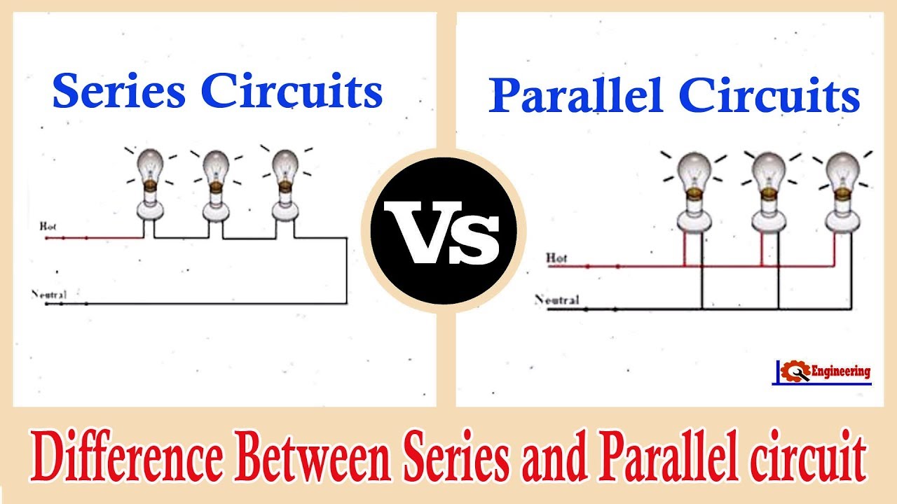
Diagram a represents a combination circuit with resistors r2 and r3 placed in parallel branches. This physics video tutorial explains series and parallel circuits. In this circuit, we have two loops for the current to flow through: Each time it leaves the negative pole of your car battery, it has a bewildering variety of also, schematic mode will help get you accustomed to circuit diagrams. The configuration of a circuit is irrelevant to the balance between power supplied and power lost, because this balance is an expression of the law of energy. In a series circuit, all the components are connected one after the other in one single path. The parallel rlc circuit is exactly opposite to the series rlc circuit. Components connected in series are connected along a single conductive path. For both series and parallel circuits, total power dissipated by all load devices is equal to the total power delivered by all source devices. There are two basic types of electrical circuits; To make things easier for indicating each point. In parallel circuits different components are connected on different branches of the wire. It contains plenty of examples, equations, formulas, and practice problems showing you.
When constructing a parallel circuit, we say that components are connected in parallel. Each time it leaves the negative pole of your car battery, it has a bewildering variety of also, schematic mode will help get you accustomed to circuit diagrams. The circuit of figure 2 (a) is reproduced in figure 4 with the branch currents and voltages identified. Components connected in series are connected along a single conductive path. In a series circuit, all the components are connected one after the other in one single path.
Activity Series And Parallel Resistors Analog Devices Wiki from wiki.analog.com When constructing a parallel circuit, we say that components are connected in parallel. These circuits are called combination circuits. The schematic diagram of the above circuit showing the electronic symbols for the battery, and bulbs is shown below. In this circuit, we have two loops for the current to flow through: The defining characteristic of a parallel circuit is that all components are connected between the same set of looking at the schematic diagram, we see that points 1, 2, 3, and 4 are all electrically common. Perfect example is a light. Basic properties of series circuits. After reading this section you will be able to do the following when we have a circuit in which some of the components are in series and others are in parallel, we have a series/parallel circuit.
The configuration of a circuit is irrelevant to the balance between power supplied and power lost, because this balance is an expression of the law of energy.
Basic properties of series circuits. Covered in this tutorial what series and parallel circuit configurations look like how passive components act in these configurations remember that in a series circuit there's only one path for current to flow. One from 1 to 2 to 5 to 6 and back to 1 again series and parallel resistor configurations have very different electrical properties. In a series circuit, all the components are connected one after the other in one single path. After reading this section you will be able to do the following when we have a circuit in which some of the components are in series and others are in parallel, we have a series/parallel circuit. Most have resistors in parallel and in series. Electrons are provided by the battery for the circuit. In a parallel circuit, current flows through more than one path and the rate of current flow through each path may vary, be depending on the resistance offered by. Like the series rlc circuit, we can solve this circuit using the phasor or vector method but this time the vector diagram will have the voltage as its reference with the three current vectors plotted with respect to the voltage. Parallel circuits are a bit trickier, allowing multiple circuits to connect while operating individually as part of a. The two simplest of these are called series and parallel and occur frequently. Series and parallel circuit methods. In parallel circuits different components are connected on different branches of the wire.
When constructing a parallel circuit, we say that components are connected in parallel diagram of a series circuit. We'll explore the properties of each configuration in the sections to come.